DLHVF speed regulation device
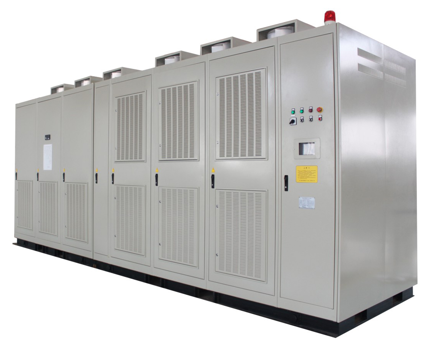
DLHVF general introduction
1. Product introduction
DLHVF series DLHVF speed regulation device is developed to adjust the speed and save energy for large or medium high voltage AC induction motors, is a kind of power unit serial connection multi-level high-high frequency converting speed regulation device. The device has following advantages: no harmonic power input, high power factor, no harmonic sine waveform output. It is widely used in frequency converting of 6kV, 10kV large power motors within power range up to 30,000 kW.
2. applicable industry
The device is suitable for:
Cement industry
Metallurgy/mining industry
Oil/chemistry
Electrical industry
Water supply industry
Waste water treatment
Pharmacy industry
Papermaking/sugaring industry
Coal-mining industry
3. Technical features
3.1 High-high direct high voltage power supply
3.2 High efficiency
3.3 High power factor
3.4 No harmonic input
3.5 No harmonic output
3.6 High reliability
3.7 High safety
3.8 Perfect protection and alarm design
3.9 High flexibility
3.10 Convenient installation and maintenance
4. Unique technical features
4.1 Waveform digital direct adaptive synthesis technology
4.2 Low voltage whole system commissioning function
4.3 Advanced auto-fault-detection technology
4.4 Withdrawable power unit
4.5 On circuit switch power units:
4.6 Power unit DC voltage on circuit test
4.7 Power unit soft bypass function
4.8 Instant torque control function:
4.9 Frequency converting soft start control technology
4.10 Motor rotate restart control technology:
5. Technical parameters
5.1 working principle
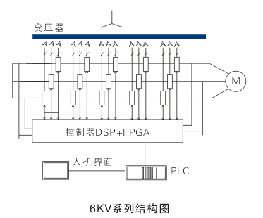
Transformer
Controller DSP+FPGA
Human-computer interface
PLC
6kV series structure diagram
Normally there are 15 power modules and every 5 power modules is serial connected as 1 phase in 6kV series.
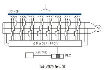
Transformer
Controller DSP+FPGA
Human-computer interface
PLC
10kV series structure diagram
Normally there are 24 power modules and every 8 power modules is serial connected as 1 phase in 6kV series.
Diagram 1: DLHVFseries DLHVF speed regulation device topological diagram
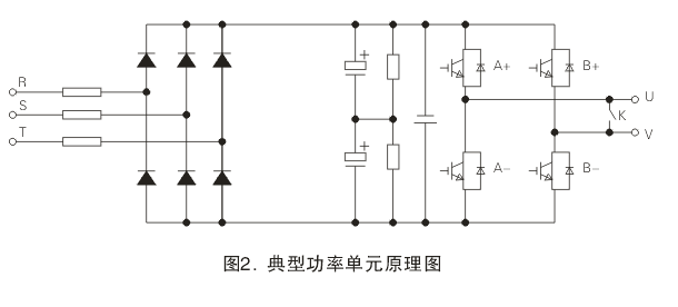
Diagram 2: typical power unit schematic diagram
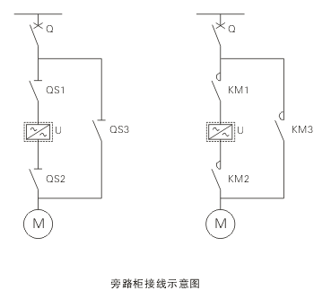
Bypass cabinet wiring diagram
6. Main technical parameters
|
item |
Standard |
description |
|
Working standard |
|
|
|
Installation site |
Indoor cabinet |
|
|
Topological structure |
Power unit multiple level serial connection to PMW voltage source |
|
|
Refitification mode |
Phase shifting multiple impulse |
|
|
Motor requirements |
Normal high voltage motor |
No requirement |
|
Input filter |
Not required |
|
|
Output filter |
Not required |
|
|
Input side fuse protection |
have |
Power unit input fuse protection |
|
Input voltage |
-30%~+15% rated voltage, frequency 45Hz~55Hz |
Service in derated capacity if voltage decrease by 15% |
|
HV input current harmony content |
<4% |
|
|
HV input power factor |
>0.96 |
|
|
HV output voltage and current harmony content |
<4% |
|
|
HV output side frequency |
5~120Hz, resolution 0.01Hz |
|
|
HV output voltage |
0~rated voltage, voltage volatility ±0.5% |
|
|
Overload capacity |
1.2 times for 1 minute, 1.5 times instant protection |
Customized available |
|
Device overall efficiency |
Full load>97%, other load>96% |
|
|
Reliability index(mean time between failures) |
25,000 hours |
|
|
Control power supply |
3-phase 4-wire AC380V, capacity 5kVa |
DC power supply also suitable |
|
HV LV control signal connection method |
Optical fiber cables |
|
|
Noise grade |
<75dBA |
(1 meter) |
|
Protection grade |
≥IP20 |
|
|
Cooling mode |
Forced air cooling |
|
|
Standard control connection |
RS485 MODBUS RTU, DP, Ethernet |
Standard industry port |
|
Analog value signal (input) |
4~20mA or 0~10V 1 way |
expandable |
|
Analog value signal (output) |
4~20mA or 0~10v 3 way |
expandable |
|
Switch value signal (input) |
10 points |
expandable |
|
Switch value signal (output) |
220v AC, 5A, 10 points |
expandable |
|
Control mode |
Touch screen |
|
|
Interface language |
Full Chinese |
|
|
Earthing requirements |
Earthing resistance <1Ω |
|
|
|
|
|
7. Type explanation
7.1 Type code
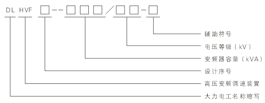
Auxiliary code
Voltage grade(kV)
Capacity of frequency converter(kVA)
Design No.
DLHVF speed regulation device
Big Pawer
Remarks: serial version design code, code 1is mainly used for fan or pump load.
Voltage grade:06-6kV 10-10kV
Auxiliary code:M—equipped with manual bypass switch cabinet A—equipped with auto bypass switch cabinet A
For example :DLHVF1-1100/06-M
Means capacity of DLHVF DLHVF speed regulation device is 1100kVA, voltage grade 6kV, suitable for fan/pump load motors, equipped with manual bypass switch cabinet.
7.2 product dimensions
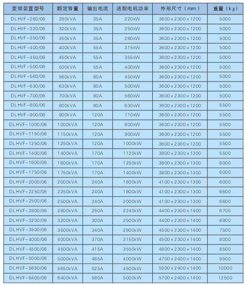
6kV DLHVF speed regulation device dimensions
DLHVF type /rated capacity/output current/motor power/dimensions/weight
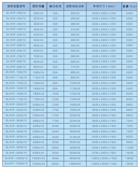
10kV DLHVF speed regulation device dimensions
DLHVF type /rated capacity/output current/motor power/dimensions/weight
Remarks:
7.2.1 The dimensions above includes phase-shifting transformer cabinet, power unit cabinet and control cabinet. Bypass cabinet is not included. The height does not include bottom base U channel (100mm) and top cooling fan (286~361mm);
7.2.2 If manual bypass cabinet is equipped, the width of bypass cabinet is 1100mm; if auto bypass is equipped, width of 6kV bypass cabinet is 600mm, width of 10kV bypass cabinet is 800mm;
7.2.3 If device dimensions are changed, the actual dimensions are subject to technical agreements;
8.2.4 Air conditioner is advised to be equipped with DLHVF. If air cooling channel is needed, please design according to site condition.
8. Ordering instructions
For the best speed regulation and energy saving efficiency, the rated capacity of DLHVF HV frequency converting speed regulation device should be determined according to actual motor load conditions. Therefore user should provide motor type, motor power, stator voltage and current data, together with driven load type and motor actual load rate.


