
DLSVG Static Var Generator
DLSVG general introduction
1. Product introduction
1.1 general
Nowadays static var generator is an important method of reactive compensation in power grid. Its fundamental principle is to detect reactive current from power grid or compensation object and generate compensating current which is opposite to the reactive current, to eliminate the reactive current and improve power factor. SVG will not be affected by power grid impedance. It adopts dynamic tracking to compensate reactive current. Its response time is short. Our SVG adopts multilevel power units ----- topological structure, integrated compensates various different loads. That is to say, it consider reactive, harmonics and negative sequence as one “distorted waveform” component. By this way it can not only dynamically absorb reactive power, improve power factor, but also absorb random harmonics. At present, SVG is an ideal device to avoid power grid “pollution”, improve power quality and save energy.
1.2 application range
Typical application conditions are as following:
1.2.1 regional power grid
1.2.2 wind power plant
1.2.3 rolling mill
1.2.4 arc furnace
2.Technical features:
SVG can automatically adjust the value and property (capacitive or sensibility) of its output reactive power. Therefore, SVG can be regarded as capacitor or reactor whose value can be continuously adjusted.
SVG is the most advanced dynamic reactive compensation technology. It does not adopt large capacitor and reactor components, and realizes the switch of reactive power by high-frequency switch of large power electrical components. Its technical features are following:
2.1 quick response
Response time of auto switching capacitor bank is several seconds and SVC approximately 20~100ms; the compensation response time of SVG device can be within 5ms. SVG can suppress voltage flicker and drop effectively and realize true dynamic compensation.
2.2 continuous compensation. The power factor can be close to 1.0.
2.3 no harmonic amplification. It can be used in power distribution system of frequency converter, induction heating power supply, controllable resistance furnace and rectifier power supply of electrolytic plating.
2.4 can generate both inductive and capacitive reactive power. It is applicable for both conditions, to improve the compensation effect and lower line loss.
2.5 output reactive will not be effected by power grid voltage. The reactive power of capacitor compensation device or SVC is in direct proportion to the square of voltage. When the voltage is low, reactive power output will significantly decrease. Normally the use ratio of capacitor compensation device is only 60~80%, meanwhile SVG is 100%.
2.6 can compensate harmonic and reactive power at the same time if necessary.
2.7 adopts H bridge cascade multilevel circuit structure, directly insert 6kV, 10kV, 27.5KV and 35kV. Besides it adopts N+1 or N+2 redundant structure. If one H bridge chain link is damaged, the device can still run with full load. Its reliability is very high.
2.8 SVG is connected to power grid and adopts LCL structure. Comparing to traditional single reactor access to power grid, SVG has following advances: applicable to any site power system impedance without resonance, ensures the reliability and safety of device; The higher harmonics generated y IGBY high frequency switch will not be ejected to power grid when SVG is working; SVG has better reactive compensation and harmonic suppression effect.
2.9 the control system of SVG adopts FPGA. The maximum clock rate of FPGA can be 200Mhz according to requirements. It concludes 84 hardware DSP digital signal processor units, 1.8 million logical gates. It is very good at digital signal processing. Therefore it can adopt more advanced algorithm to improve the performance of SVG.
2.10 new type control algorithm and mudulation mode, together with super computing ability enhances the harmonic filtration ability of SVG device. It can filter all harmonics within 30 times with over 97% filtration efficiency.
2.11 high reliability: design of SVG follows HV national mandatory standard. HV main circuits and control circuits are connected by optic fiber which is safe and reliable.
2.12 perfect protection and fault alarm design including system and power units protection, fault auto record and memory functions which can automatically record the protection action type and action time to help the technicians locate the fault and analyze the cause.
2. 13 high flexibility:SVG can be control by PLC on site. Its control mode can be changed by set parameters via human-computer interface. Various standard communication protocols available for communication with central control system.
3.Technical parameters
3.1working principle
SVG dynamic reactive power compensation device adopts multilevel power units cascade topological structure, via parallel connection with system, real-time detect harmonic and reactive power component of load, with PWM conversion technology, injects current which is same in value and opposite in direction to harmonic and reactive power components, into power distribution system, to realize harmonic suppression and dynamic reactive power compensation functions.
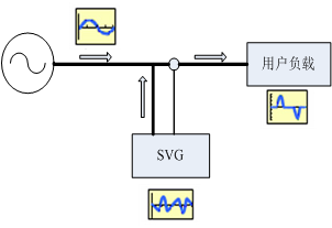 right side: user load
Diagram 3.1 SVG functional block diagram
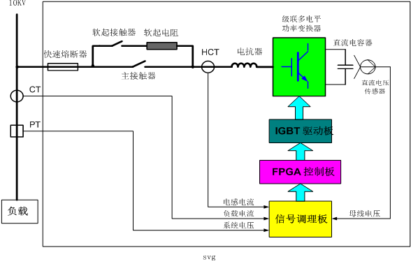
Diagram 3.2 schematic diagram of SVG main circuits
|
Running mode |
Waveform and phasor diagram |
description |
|
No load running mode |
|
UI = Us,IL = 0,SVG does not absorb and generate reactive power |
|
Capacitive running mode |
|
UI > Us,IL is advanced current, its amplitude can continuously controlled by adjusting UI,to continuously control reactive power generated by SVG |
|
Inductive running mode |
|
UI < Us,IL is hysteresis current. At this time the reactive power which is absorbed by SVG can be continuously controlled. |
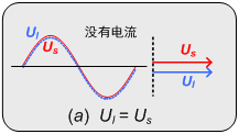
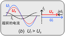
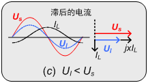
Diagram 3.3 three running mode of SVG
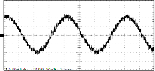
Diagram 3.4 overall output waveform
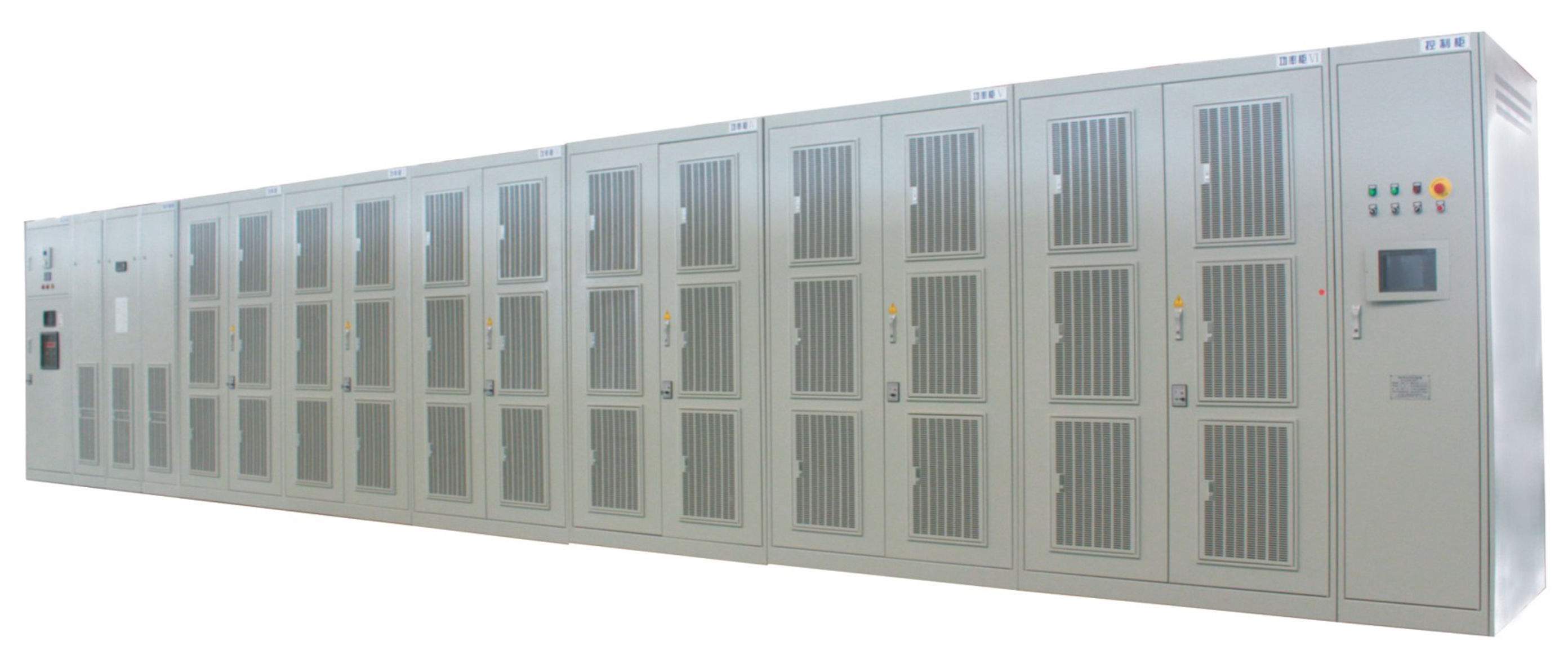
3.2 components of DLSVG
The DLSVG device consists of control cabinet, power cabinet, start cabinet. The isolation switch is connected with power grid.
3.3 control and protection system functions
3.3.1 As the modulation process is non-linear, there is error with calculation parameters, and there are shift and drift factors in whole system, the device must adopt close-loop control to reach the control accuracy and response speed requirements.
3.3.2 protection functions
System over current protection
System over voltage protection
System under voltage protection
Unit over voltage protection
Unit over heat protection
Unit short circuit protection
Unit communication anomaly protection
Device door open alarm
3.4 main technical parameters
|
Item |
Standard |
Remark |
|
Using standard |
Q/XDL 18-2015 |
|
|
Installation place |
Indoor cabinet type |
|
|
Topological structure |
Power units parallel connected to PWM voltage source |
|
|
Power grid voltage |
(+10%-20%) rated voltage, frequency 50Hz(±5%) |
|
|
Compensation harmonic range |
2~25 times |
|
|
Response time |
<5ms |
|
|
Switch frequency |
6kHz(average) |
|
|
Active power loss |
<5% |
|
|
Reliability standard(mean time between failures) |
25000 hours |
|
|
Power unit control signal connection method |
Optic fiber cable |
|
|
Noise grade |
<65dBA |
(1 meter) |
|
Protection grade |
≥IP20 |
|
|
Cooling method |
Forced air cooling |
|
|
Operation mode |
Touch screen |
|
|
Interface language |
Full Chinese |
|
|
Earthing |
Earthing resistance <1Ω |
|
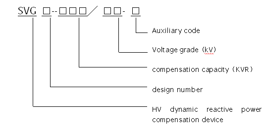
4.Type explanation
|
Type |
Voltage grade |
Rated capacity |
External dimensions |
|
DLSVG-2000/06 |
6kV |
2000kvr |
2400*2300*1300 |
|
DLSVG-4000/06 |
6kV |
4000kvr |
4800*2300*1300 |
|
DLSVG-5000/06 |
6kV |
5000kvr |
4800*2300*1300 |
|
DLSVG-1000/10 |
10kV |
1000kvr |
2400*2300*1300 |
|
DLSVG-2000/10 |
10kV |
2000kvr |
2400*2300*1300 |
|
DLSVG-4000/10 |
10kV |
4000kvr |
4800*2300*1300 |
|
DLSVG-5000/10 |
10kV |
5000Kvr |
4800*2300*1300 |
|
DLSVG-8000/10 |
10kV |
8000kvr |
7800*2300*1200 |
|
DLSVG-10000/10 |
10kV |
10000kvr |
7800*2300*1200 |
|
DLSVG-15000/10 |
10kV |
15000kvr |
7800*2300*1200 |
5.Ordering instructions
For better reactive power compensation and filtration effect, the rated capacity should be determined according to actual power grid compensation conditions.
Therefore user should provide power grid parameters, system running voltage, current, active power, reactive power, power factor, harmonic components information. Big Pawer can take power quality monitors and other devices to site for help if necessary.


