GGD type complete set switch device
1. General
1.1 Brief introduction
GGD type complete set switch device is designed according to safe, economic, proper, reliable principles, to meet the requirements of various electric users, to meet the requirements of capacity increase, computer port, power center control, installation and maintenance, decrease fault remedy time. With its good open/close ability, flexible electric scheme and combination, strong practicability, novel structure, high protection grade and other features it can be the replacement product of old low voltage complete set switch cabinet devices.
This product is a typical Chinese assembly type, fixed panel switch cabinet.
1.2 Application range
GGD type AC low voltage power distribution cabinet is suitable for electric users including power plant, substation, industrial mining enterprise.
1.3 Technical features
GGD type AC low voltage power distribution cabinet is equipped in AC 50Hz, rated working voltage 380V, maximum rated current 3150A power distribution system for the power conversion, distribution and control of motor, lighting and power distribution devices. Its breaking capacity is high with maximum 50kA short time withstand current. Its is flexible in wiring scheme, convenient to assemble, good in practicability, novel in structure.
2. Technical parameters
|
Type |
Rated voltage(V) |
Rated current(A) |
Rated short-circuit breaking current (KA) |
Rated short time withstand current (IS)(KA) |
Withstand current (KA) |
|
GGD1 |
380 |
A 1000 |
15 |
15 |
30 |
|
B 600(630) |
|||||
|
C 400 |
|||||
|
GGD2 |
380 |
A 1500(1600) |
30 |
30 |
63 |
|
B 1000 |
|||||
|
C |
|||||
|
GGD3 |
380 |
A 3150 |
50 |
50 |
105 |
2.1 Service conditions
■ Ambient air temperature maximum +40℃, minimum -5℃, 24 hours average temperature maximum +35℃.
■ air clean, relative humidity maximum 50% in temperature +40℃, in lower temperature more relative humidity is allowed, for example 90% in +20℃. Considering temperature change, occasional condensation is possible.
■ Maximum altitude 2000m
■ Pollution grade level 3.
■ Maximum horizontal gradient 5% during installation.
■ Should be installed indoor without strenuous vibration, impact and corrosion.
■ If above-mentioned service conditions can not be met, user shall communicate with manufacturer.
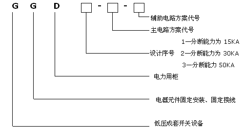
2.2 Type explanation

Auxiliary circuit scheme code
Main circuit scheme code
1. Breaking capacity 15kA
Design No. 2. Breaking capacity 30kA
3. Breaking capacity 50kA
Electric cabinet
Fixed components and wiring
Low voltage complete set switch device
3. Ordering instructions
Following documents should be provided to manufacturer before ordering
n All type of product (including main circuit scheme and auxiliary circuit scheme)
n Main circuit system assembly sequence diagram
n Auxiliary circuit electrical schematic diagram
n Components list
n Other special requirements
4. Product certifications
CCC certification


